 | ||||||||||||||||||||||||
| 9 - 1 - 1 System Lesson | ||||||||||||||||||||||||
| The table below provides links to materials which are relevant and applicable across all of the courseware in this program. For ease of access, this table is reproduced on every page of each lesson. | ||||||||||||||||||||||||
| ||||||||||||||||||||||||
| ||||||||||||||||||||||||
| Introduction The emergency reporting system, commonly known as 9-1-1, is a standardized system for reporting emergencies over the telephone network. The requirements for an emergency reporting system include: | ||||||||||||||||||||||||
| ||||||||||||||||||||||||
| The emergency reporting system originated in Great Britain as the 9-9-9 emergency telephone system established in 1937. The first US 9-1-1 system was set up in Haleyville, Alabama on February 16, 1968. Since that time systems have been implemented in most cities, counties or regions in the United States. | ||||||||||||||||||||||||
| ||||||||||||||||||||||||
9-1-1 Web Sites
| ||||||||||||||||||||||||
| The Public Switched Telephone Network (PSTN) To understand how the 9-1-1 system operates, we must first know a little about how the telephone system operates. The provision of telephone service ansd the portfolio of services has changed dramatically in recent years and is still changing. We are going to take a simplified approach that is historical and focuses on wire providers, cellular providers and Internet providers. Historically the telephone network in the United States was a hierarchical network consisting of two types of companies:
An end office might host the equipment for one or more exchange. Telephone numbers are set and managed by the North American Number Plan Authority (NANPA). See www.nanpa.com. Our telephone numbers consist of three parts:
| ||||||||||||||||||||||||
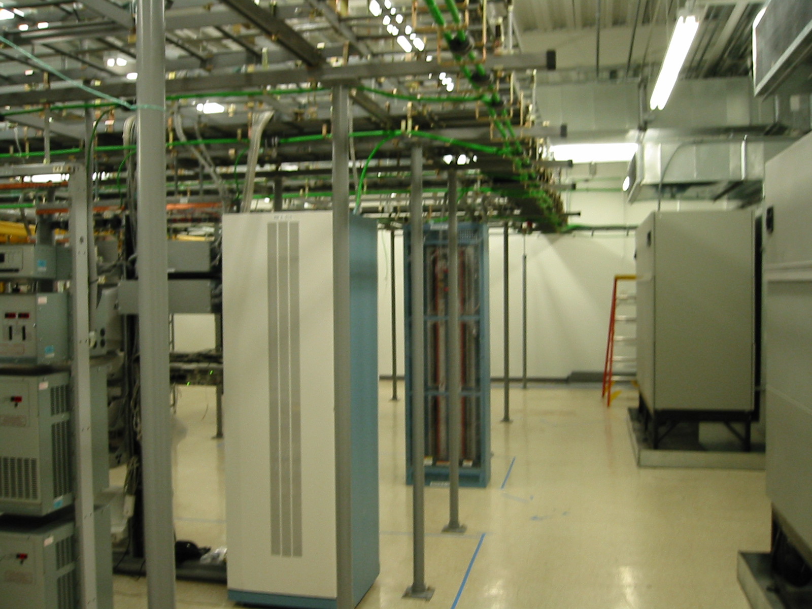 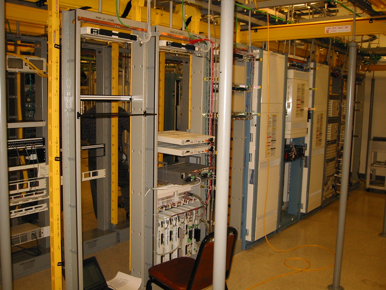 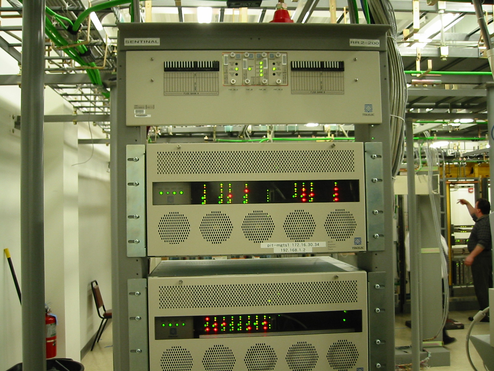 Telephone Central Office or End Office | ||||||||||||||||||||||||
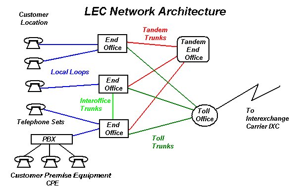 | ||||||||||||||||||||||||
| When a customer (subscriber) picks up his or her telephone, a connection is signalled to the end office that serves that custoner. Equipment in the end office captures the number dialed. Each telephone office has one or more switches that routes the call based on the number captured. If the number is for a customer served by the same end office then the two customers are connected through the end office. When the number is for a different local end office, if the end offices are connected by a trunk, then the call is routed through the trunk. Otherwise, the call is routed through the tandem end office. Calls that are for subscribers within the region are routed through the toll office. Calls out of the area code are routed through the toll office to the IXC. | ||||||||||||||||||||||||
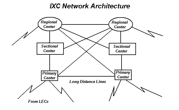
| The diagram below shows the architecture for the Interexchange Carriers. These networks connect the local carriers. Calls that traverse these networks are long distance calls. | ||||||||||||||||||||||||
 | ||||||||||||||||||||||||
| The Phone System in Emergencies | ||||||||||||||||||||||||
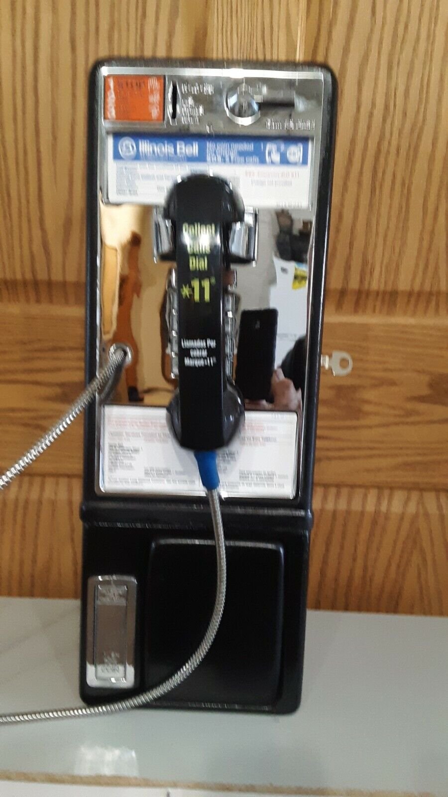
| The local telephone system operates of of 48 volt direct current (DC) power. This system is completely independent of the electrical network. The phone lines are powered by banks of batteries in the central office. In some emergencies when electrical power has failed, the wireline phone system will still work. The phone company has emergency generators to keep the batteries recharged. Some subscribers have updated their phones using cordless phones that can be carried around. These phones will not work when the power goes out because the base station relies on the house power. For emergency purposes, it is advisable to keep around an old style telephone set that that will continue to operate when the power goes out. | ||||||||||||||||||||||||
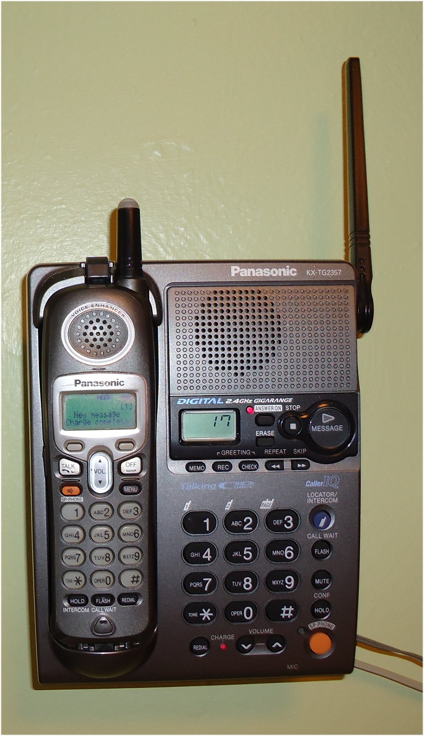 Cordless Telephone | ||||||||||||||||||||||||
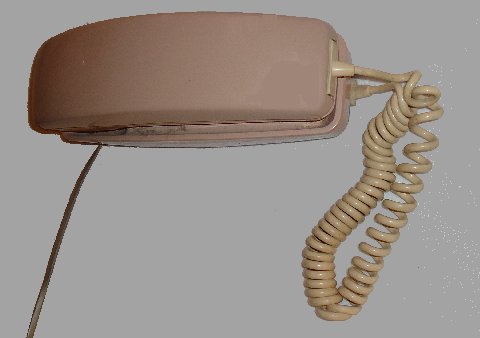 Standard Telephone | ||||||||||||||||||||||||
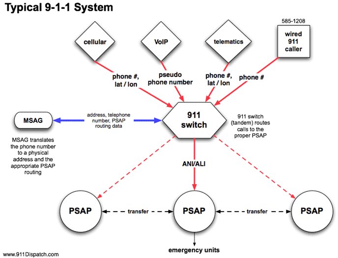
| The 9-1-1 System The 9-1-1 system was developed to allow the reporting of emergencies rapidly, efficiently and without error. The diagram below shows the architecture of a modern 9-1-1 system. Originally 9-1-1 was developed to serve wireline telephone users. The service was quickly expanded to support handicapped users (deaf, non-speaking and others). The basic idea here was that since everyone was physically attached to the end of a line (wire) the location of the caller could be easily determined. When someone dialed the special code 911, that call would be directed through the phone network From an end office or a tandom office to a 9-1-1 switch as shown in the diagram. | ||||||||||||||||||||||||
 | ||||||||||||||||||||||||
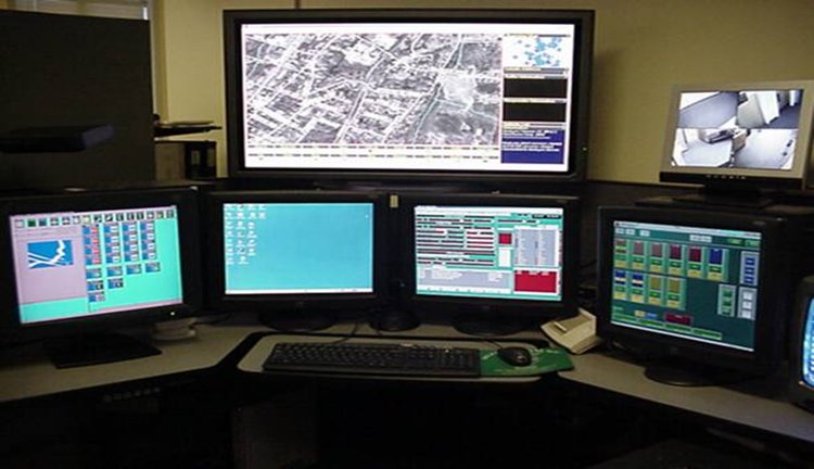
| When a customer makes a 9-1-1 call, the end office routes the call to a 9-1-1 switch. The switch looks up the number in a database called the MSAG (Master Street Address Guide). The MSAG contains address data for all subscribers. The lookup returns the name, address and the PSAP (Public Service Answering Point) closest to the customer. The switch uses this data to route the call to the PSAP And passes the MSAG data along to the PSAP. The PSAP is where the local emergency dispatchers are housed. A 9-1-1 dispatcher receives the call and, based up an established protocol, sends the nearest and appropriate police, fire, EMS or other units to the customer's location. The picture below shows a typical dispatcher's workstation in the PSAP. Pittsburgh's PSAP is co-located with its Emergency Operations Center (EOC) located in the Point Breeze section of the city. | ||||||||||||||||||||||||
 | ||||||||||||||||||||||||
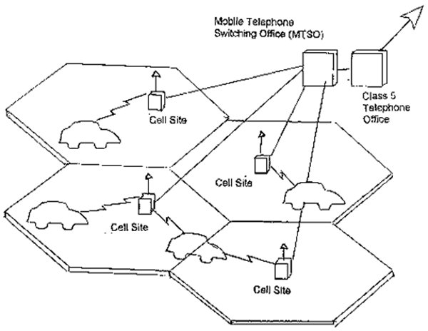
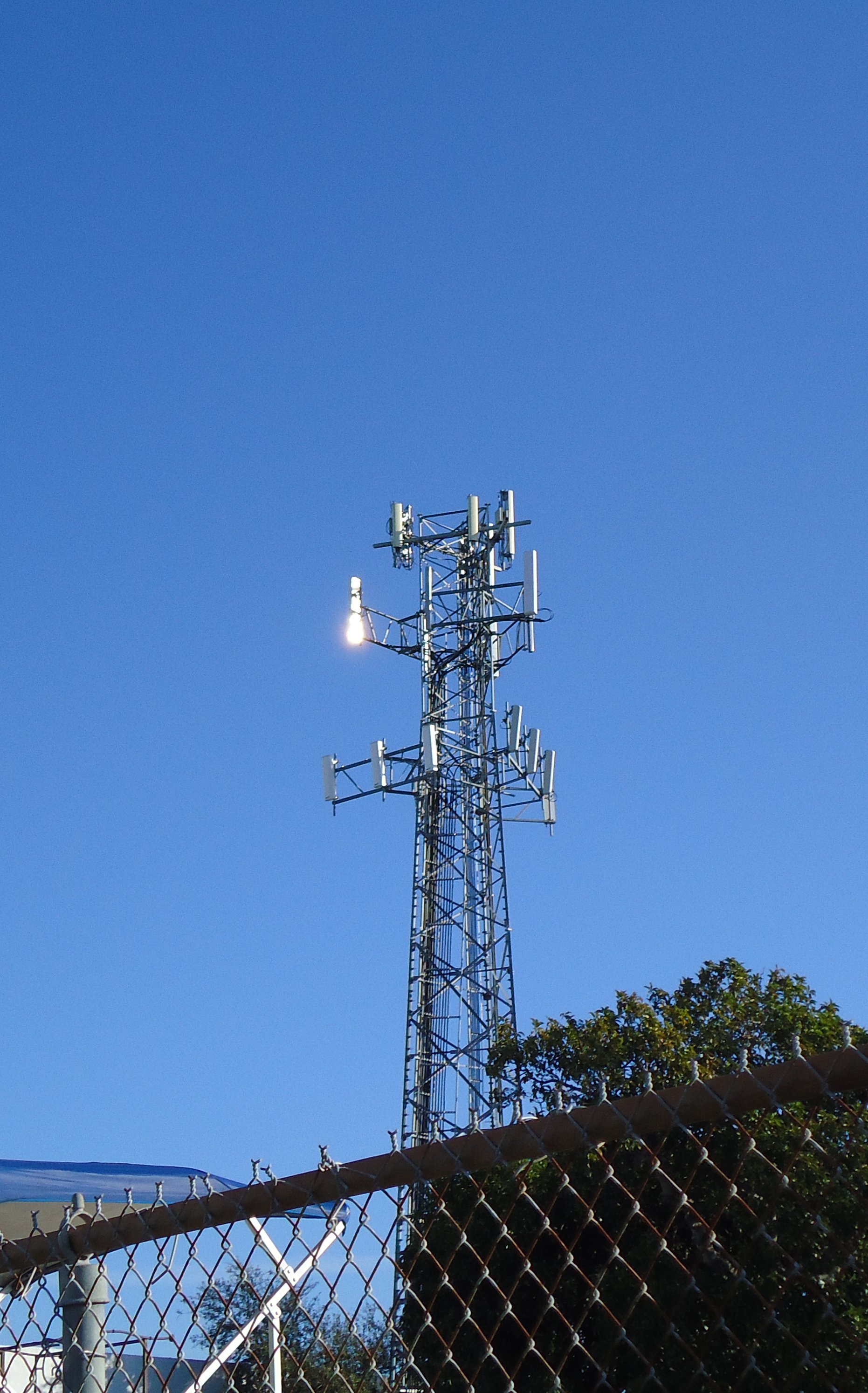
| The Cellular Telephone System The schematic below shows the architecture of the cellular telephone network. The customer (subscriber) has a telephone unit that communicates via radio with a cell tower. The system is designed so that there are numerous cell towers covering a region. At any time, a given subscriber's call is controlled by the cell site closest to him or her. The neighboring cells can detect the communication. When the customer moves from one cell to another, called roaming, the system automatically assigns the new cell cite as the controlling site. Call channels are allocated so that two adjacent cells do not use the same channel. Each of the cell sites is connected to a cell end office called the Mobile Telephone Switching Office (MTSO). The MTSO is connected by trunks to the Public Switched Telephone Network. This architecture allows cell phone users to call other cell phone users as well as wireline subscribers. | ||||||||||||||||||||||||
 | ||||||||||||||||||||||||
  | ||||||||||||||||||||||||
| Cellular telephony initially provided some challenges to the 9-1-1 system. Because the cell phoen could be anywhere, the MSAG data did not give dispatchers a location to dispatch emergency equipment to. Often the callers did not know where they were. As a stopgap measure, some cellular providers provided a service by which the location of the cell phone was approximated using triangulation from the known positions of the cell towers. Next generation telephones which have Global Positioning System (GPS) capabilities built in and can transmit these to the phone company along with the call. | ||||||||||||||||||||||||
| VOIP (Voice Over Internet Protocol) Many subscribers are using the Internet to make telephone calls through services such as Skype www.skype.com. These people can use their telephones or more usually their computers to make these calls. The customer is connected to or dials up a business called an Internet Service Provider (ISP). The ISP is connected to the Internet Service Provider is connected to the Internet directly or through a common carrier. The call is carried through the Internet which completes the call through the local carrier. This arrangement created the same kinds of problems that cellular telephones did (i.e. the 9-1-1 dispatcher did not know where the call was coming from. Efforts are being made to relate IP addresses to physical addresses to remedy theis problem. | ||||||||||||||||||||||||
|
9-1-1 Operations 9-1-1 service has evolved over the years and continues to evolve as technology changes. The sections below outline the types of 9-1-1 currently in use or planned.
| ||||||||||||||||||||||||
| Basic 9-1-1 | ||||||||||||||||||||||||
| When the three-digit number is dialed, a call taker/dispatcher in the local public safety answering point (PSAP), or 9-1-1 call center, answers the call. The emergency and its location are communicated by voice (or TTY) between the caller and the call taker. | ||||||||||||||||||||||||
| Enhanced 9-1-1 | ||||||||||||||||||||||||
| The call is selectively routed to the proper PSAP for the caller�s location, and the PSAP has equipment and database information (MSAG) that display the caller's phone number and address to the call taker. | ||||||||||||||||||||||||
| Wireless Phase I | ||||||||||||||||||||||||
| The call taker automatically receives the wireless phone number. This is important in the event the wireless phone call is dropped, and may allow PSAP employees to work with the wireless company to identify the wireless subscriber. Phase I also delivers the location of the cell tower handling the call. The call is routed to a PSAP based on cell site/sector information. | ||||||||||||||||||||||||
| Wireless Phase II | ||||||||||||||||||||||||
| Phase II allows call takers to receive both the caller's wireless phone number and their location information. The call is routed to a PSAP either based on cell site/sector location information. | ||||||||||||||||||||||||
| VoIP | ||||||||||||||||||||||||
| Business and residential use of Voice over Internet Protocol (VoIP) telecommunications services is growing at a rapid pace. Addressing for VoIP is being added to protocols. | ||||||||||||||||||||||||
| Reverse 9-1-1 | ||||||||||||||||||||||||
| In an emergency, a dispatcher can bulk call a list of numbers and deliver a message simultaneously. Selection of this list can be by geographic area or other criteria. In effect this is a targeted alert system. | ||||||||||||||||||||||||
| Coverage | ||||||||||||||||||||||||
| As of February, 2021, the United States has 5,748 (6,143) primary and secondary PSAPs and 3,135 Counties which include parishes, independent cities, boroughs and Census areas. | ||||||||||||||||||||||||
| ||||||||||||||||||||||||
| Call Volume | ||||||||||||||||||||||||
| An estimated 240 million calls are made to 9-1-1 in the U.S. each year. | ||||||||||||||||||||||||
| According to the FCC, most calls are wireless calls. Example 9-1-1 Call Center call statistics from US in 2021. | ||||||||||||||||||||||||
| ||||||||||||||||||||||||
| Situation Awareness A 9-1-1 call is the first alert that an emergency is or may be happening. An emergency operator's job is to diagnose and provide a record of the call. Many jurisdictions have developed Call Scripts to aid the 9-1-1 oerator in his or her task. The following Call Scripts are from Eugene, Oregon https://www.eugene-or.gov/2892/9-1-1-Call-Scripts. What You Will be Asked, and Why People are often in stressful situations when they call 911. Before being put in this position, it�s helpful for you to understand what kinds of questions you�ll be asked when you access the 911 system. The call flow will go much smoother when the call taker is allowed to ask you questions in the order the information is needed. Please note that if you have a cell phone, you should review the topics to the right under How to Use 911. The following are some guidelines for the information that will commonly be required: What is the address of the emergency?
This is the number to the phone you�re actually dialing 911 from. Again, if your home phone number, or an alternate number is required, it will be asked for later. It is important for us to have this information in case we need to call you back to ask more questions, clarify directions, give further instructions, etc. What is your name? Please don�t be insulted if we ask you to clarify, or spell your name. There are many spelling variations when it comes to names and it�s important we obtain correct information. Tell me exactly what happened.
For medical calls, you will be asked the following questions
For fire calls, you may be asked the following questions
In a police situation, you may be asked the following questions
| ||||||||||||||||||||||||
| Most of the calls to 9-1-1 are not emergencies or minor emergencies. Following are examples of the wide range of calls that a 9-1-1 system and its operators must deal with: | ||||||||||||||||||||||||
| Trends Estimates are that over 29.7% of all U.S. households currently rely on wireless as their primary service. VoIP is growing at an accelerated rate. Text messages may not be the most effective. | ||||||||||||||||||||||||
| Security Systems Technological advancements have made security features more economical for home use. The are also advantageous for 9-1-1 systems. Security vendors provide monitoring and triage for alarms such that unecessary calls are not made. Some securityy vendors have patrols that are the first situation awareness responders. Security System Vendors The list below gives some of the popular commercial and home system vendors:
Security System Features Selected Examples:
| ||||||||||||||||||||||||
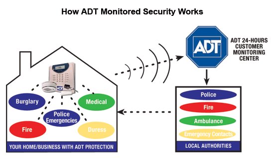 Typical Alarm System Architecture | ||||||||||||||||||||||||
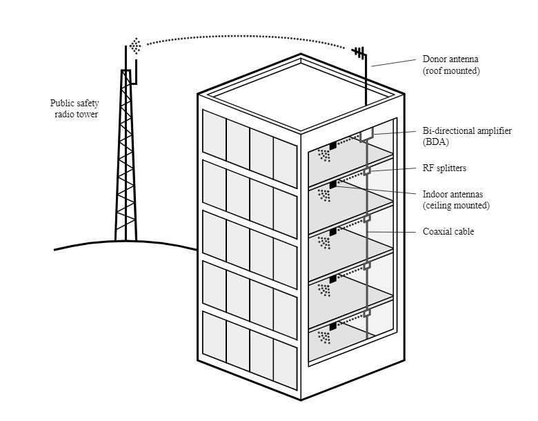 Typical CommercialAlarm System Architecture | ||||||||||||||||||||||||
 Typical Alarm System ContrilPanel | ||||||||||||||||||||||||
| The N11 System | ||||||||||||||||||||||||
|
As a result of many calls to 9-1-1 not being made for emergency purposes, authorities have developed an expanded three digit dialing system for non-emergency services. An N11 number is a special abbreviated dialing telephone number within the North American Numbering Plan www.nanpa.com , which directs access to special services. | ||||||||||||||||||||||||
| Usage is assigned as follows: | ||||||||||||||||||||||||
| ||||||||||||||||||||||||
| ||||||||||||||||||||||||
| Government Emergency Telecommunications Service The Government Emergency Telecommunications Service (GETS) is a service available to emergency personnel. GETS is a priority service that allows critical calls to get through in times of emergency when the phone system may be clogged. The image below shows the agencies that participate in the GETS program. | ||||||||||||||||||||||||
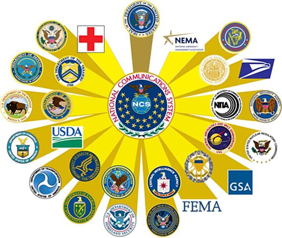 | ||||||||||||||||||||||||
The GETS Network is composed of common carriers that provide telecommunications services to the government on a regular basis:
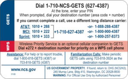
The GETS system can be accessed through:
| ||||||||||||||||||||||||
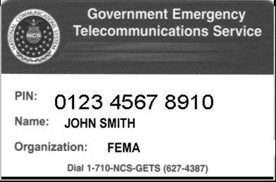
| Qualified recipients receive a GETS card that contains all of the pertinent information for system use. Both sides of a sample card are shown below. | ||||||||||||||||||||||||
  | ||||||||||||||||||||||||
| Emergency Communications at Pitt | ||||||||||||||||||||||||
| ||||||||||||||||||||||||
|
For voice, the caller ID will display as 412-624-1526. We recommend that you add this phone number to your address book as "Pitt ENS" so that you will recognize it immediately. For text, the message will be sent from 41526. For email, the message will be sent from ens@pitt.edu.
On March 8, 2012 a gunman killed one and injured seven in an atttack at the Western Psychiatric Clinic on the Pitt Campus. The Emergency Notification System was used to notify and provide instructions those enrolled while the event was taking place. See the story in the Pitt News. | ||||||||||||||||||||||||
| ||||||||||||||||||||||||
| ||||||||||||||||||||||||
| Navigation | ||||||||||||||||||||||||
| ||||||||||||||||||||||||
| Copyright © 2011 - 2023 Ken Sochats | ||||||||||||||||||||||||